blog categories
recent posts
blog tags

In the family of electronic components, although inductors and transformers both belong to magnetoelectric conversion components, their structural compositions have significant differences due to different functional orientations. This article will take transformers of models EM15 and EE19, as well as uu10.0 common mode inductors and ferrite rod inductors as examples to analyze the core differences in their compositions.
1. Number of Coils: The Functional Distinction Between Single Winding and Multiple Windings
As the core carrier of energy conversion, the number of coils directly determines the basic function of the component.
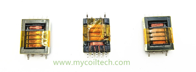
Both EM15 and EE19 are typical transformers, and their core feature is that they contain at least two independent windings. Taking the EE19 transformer as an example, the primary coil is connected to the input voltage, and the secondary coil outputs the converted voltage. The two groups of coils realize energy transfer through magnetic core coupling, and there is no electrical connection between them. The SMD-EM15 high frequency electronic transformer is often designed with a multi-winding structure. In addition to the primary coil, it may contain 2-3 sets of secondary coils to meet the voltage requirements of different circuits. This multi-winding design is the basis for transformers to achieve voltage transformation, isolation, and impedance matching.
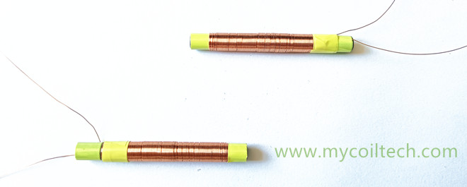
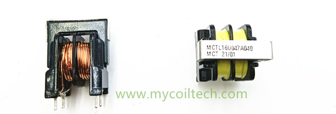
The coil design of inductors follows the "single winding" principle. Although the uu10.0 common mode inductor has two groups of coils in appearance, the two groups of coils have opposite winding directions and the same number of turns, which essentially belong to an "integrated single-function winding" and work together to suppress common mode interference. The structure of the ferrite rod inductor is simpler, with only a single group of coils wound on a ferrite rod. The number of coil turns is adjusted according to the required inductance. For example, the ferrite rod inductor used for receiving low-frequency signals in a radio usually has hundreds to thousands of turns. The single winding design enables it to focus on realizing signal filtering or energy storage through self-inductance.
2. Magnetic Core Structure: The Design Logic of Closed Magnetic Circuit and Open Magnetic Circuit
The magnetic core is the key factor affecting the efficiency of energy conversion. The difference in magnetic core structure between inductors and transformers stems from different functional requirements.
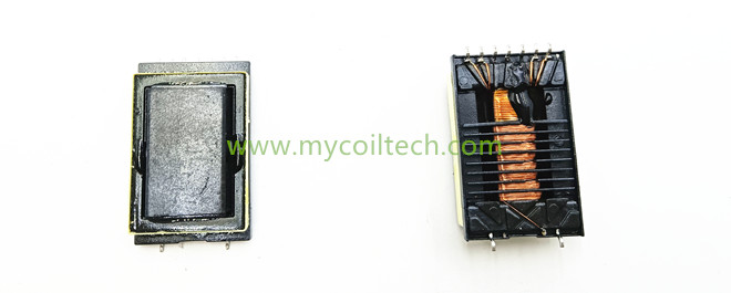
The magnetic core of a transformer must adopt a closed magnetic circuit design to maximize the magnetic coupling efficiency between windings. The magnetic core of the SMD-EE19 transformer 7+2 Pins is an E-type spliced structure. The upper and lower yokes and the middle column form a closed magnetic circuit, so that the magnetic field generated by the primary coil is almost completely transmitted to the secondary coil through the magnetic core, and the magnetic leakage rate can be controlled within 5%. The EM15 transformer mostly uses a pot-type magnetic core, which completely wraps the windings inside the magnetic core, further reducing magnetic leakage and ensuring that the energy transfer efficiency exceeds 95%. This closed structure is the core guarantee for transformers to achieve efficient voltage transformation and isolation functions.
The magnetic core of an inductor aims to "optimize self-inductance performance" and mostly adopts an open magnetic circuit. The magnetic core of the uu10.0 common mode inductor is a U-type spliced structure. The two groups of coils are respectively wound on the magnetic columns on both sides. Although the magnetic circuit is not completely open, the deliberately retained small air gap can reduce the risk of magnetic saturation, making it suitable for high-current scenarios. The magnetic core of the single winding ferrite rod inductor is a completely open rod-shaped structure (usually made of ferrite material). The coil is wound along the axial direction of the ferrite rod, and the magnetic field can diffuse to the external space. Although this design will reduce the magnetic coupling efficiency, it can significantly improve the frequency response range of the inductor, making it perform excellently in high-frequency scenarios such as radio tuning.
3. Additional Structures: Different Orientations of Function Enhancement and Simplicity and Practicality
To adapt to different working environments, the additional structures of the two also show obvious differences.
Transformers need to cope with high-voltage and high-current scenarios, and their additional structures focus on "safety and efficiency". The windings of EE19 and EM15 transformers are provided with multiple insulating layers (such as polyimide films), and the voltage resistance level can reach more than 2000V; some high-frequency models will also add a copper foil shielding layer between the primary and secondary to suppress electromagnetic interference. Large industrial EM15 transformers are also equipped with iron core clamping devices to avoid noise caused by vibration of silicon steel sheets.
The additional structure of the inductor is more concise. The UU15.7 anti interference inductor only fixes the coil and magnetic core through shell packaging, without an additional insulating layer (because the working voltage is low); the structure of the ferrite rod inductor is simpler, usually only plastic brackets are added at both ends of the ferrite rod to fix the coil, and some models are coated with insulating paint to prevent coil short circuits. This simple design enables it to adapt to the installation needs of miniaturized equipment (such as portable radios).
4.Conclusion: A Typical Example of Function Determining Structure
It can be seen from the above models that the multi-winding, closed magnetic circuit, and complex additional structures of transformers all serve "efficient energy transfer and conversion"; while the single-winding, open magnetic circuit, and simple design of inductors focus on "current obstruction and signal filtering". Understanding these compositional differences can not only help us quickly identify component types but also accurately select models in circuit design - for example, using the EE19 transformer to achieve power supply step-down, and using the ferrite rod inductor to optimize the receiving sensitivity of the radio, so that each type of component can play its maximum role in the right position.
5.Finally, regarding our company
We have been rooted in the electronic components industry for over 10 years and own a variety of special-sized transformers such as bobbin. We specialize in the production of transformers, inductors, current mutual inductance filters, and so on. As a professional electronic component manufacturer, we have our own team of technical engineers dedicated to solving customers' problems, providing customized services for them, and helping your project reach the forefront of the industry.
Contact us today to explore bulk orders or request technical specifications.
Email: sales008@mycoiltech.com
Whats app ID: +86 18788862885
Name:Alex~Mycoiltech
